Haythorn and Stuart

HAYTHORN & STUART, Engineers and Brass Founders, Eastwood Works, Pollokshaws, Glasgow. Telegraphic address: “Haythorn”, Pollokshaws.

    Amongst the more recent additions to the ranks of industrial enterprise in this great centre of activity, special distinction must be assigned to the important undertaking inaugurated about two years ago by Messrs. Haythorn and Stuart, Engineers, Brass Founders, etc., to which we have pleasure in directing the attention of our readers.

    The premises occupied by the firm are of commodious proportions and are situated in convenient proximity to the railway, from which a siding provides facilities for the transit of materials and finished goods. The works cover a total area of about four acres, on which are erected the buildings requisite for the various departments, including spacious machine shops 250 feet in length and 32 feet wide, brass finishing and smiths’ shops of similar dimensions, and foundries fitted throughout with modern plant and machinery of improved construction, for which motive power is derived from a 40 h.p. engine. The other buildings comprise large pattern shop 50 feet by 30 feet, brass-finishing department, and extensive stores for material, &c.

    The principal productions of the firm include the construction of plant and machinery for steel manufacturers, in which department they have recently completed an important contract for the fitting up of the Dumbarton Steel Works, and have also undertaken similar work in connection with the manufacture of machinery for the leading dyers and calico printers in the district ; they are also makers of all descriptions of marine and land engines.

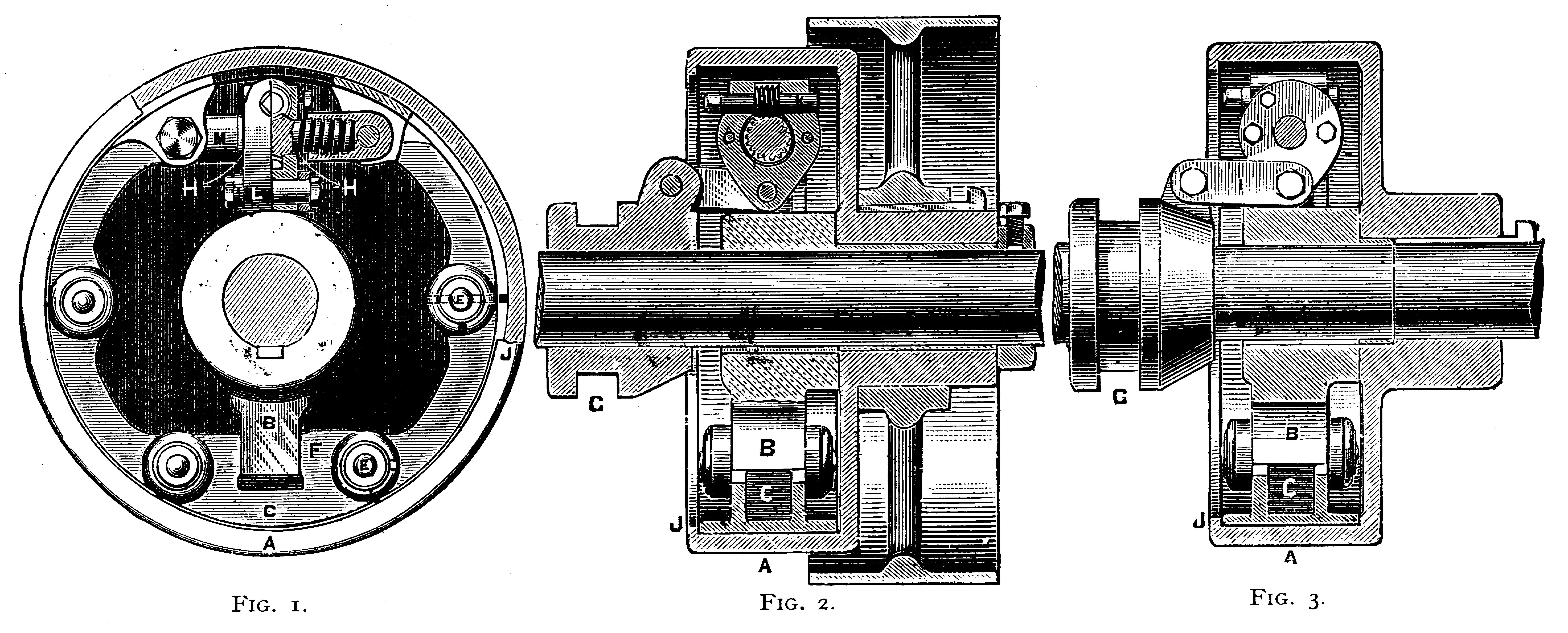
    Messrs. Haythorn and Stuart are also the patentees and sole makers of the patent Friction Clutch and Coupling illustrated below, an appliance designed to effect greater economy in the distribution of steam power and, consequently, fuel, and running shafting unnecessarily — obviating the manifest danger of common clutches — rapidity of application in stopping momentarily a line of shafting or any section of it in cases of accident, and possessing in every sense a marked advantage in the methods of starting and stopping machinery in motion.

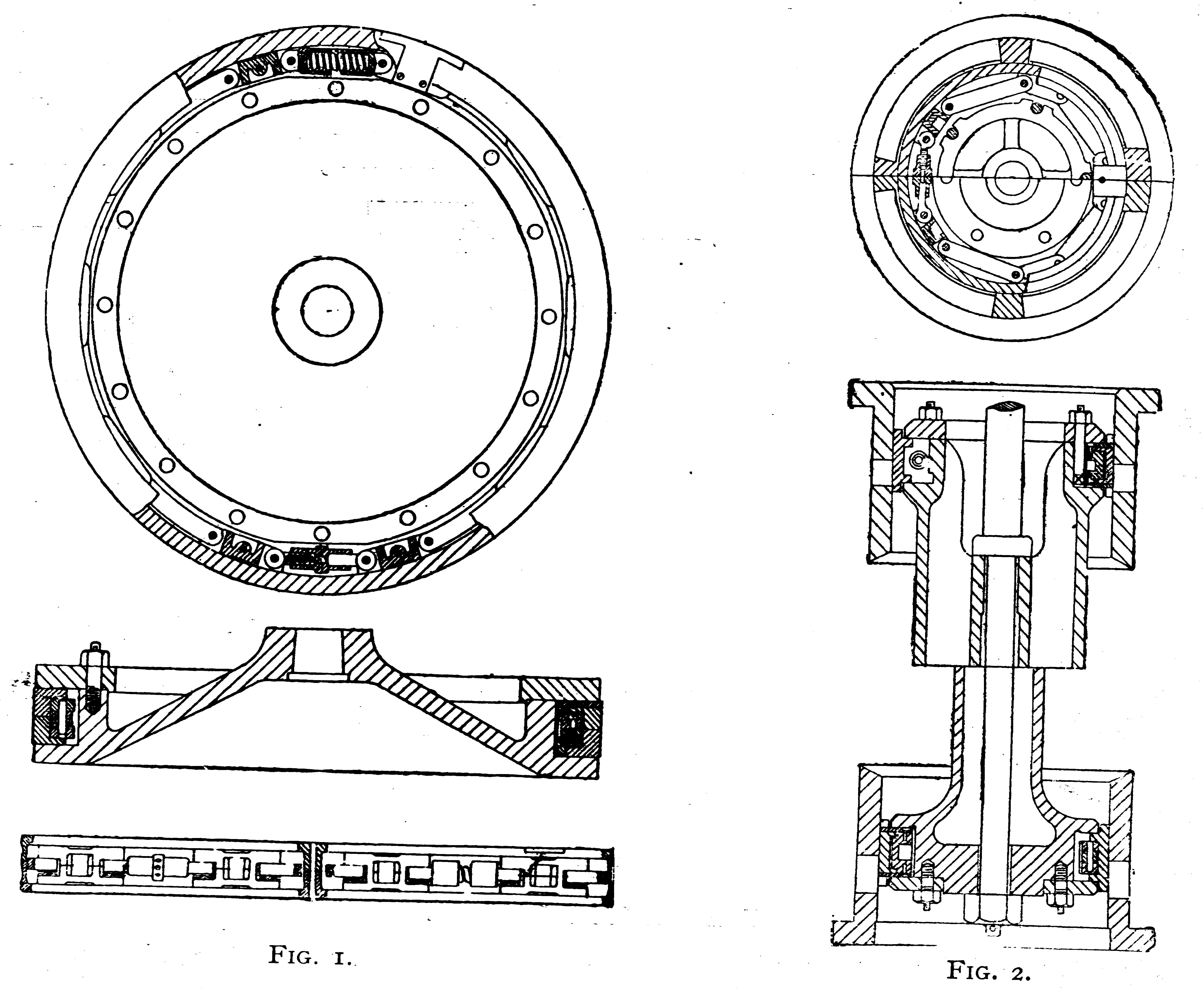
    The firm are also manufacturers of Haythorn’s patent pistons and piston valves, of which we also give illustrations. Those represent the nearest approach to perfection in theory and practice in these important parts of the mechanism of an engine, and have, after five years’ successful use, under all conditions of working, and up, to nearly 100 inches in diameter, justified the patentees in guaranteeing to the users of these pistons and valves an economy or increased effective power of at least 5 per cent, in each instance, beside the great saving in repairs, renewals, and disuse of lubricants. They are also patentees and makers of a practically perfect form of metallic packing for piston rods and plungers. Fuller details of these appliances are supplied in pamphlets, illustrated with plans and sections, to be obtained from the firm, who will at any time afford opportunities of inspection to those desirous of viewing their specialties in operation.

    The works employ the services of a large staff of skilled hands in the various departments under the experienced direction of the principals, whose thoroughly practical knowledge of every branch of the business ensures perfection of finished workmanship in the execution of all contracts and orders entrusted to them for completion. In conclusion, we may mention that the firm have already established a wide-spread and valuable connection in all parts of the United Kingdom, their principal agencies being — London, Mr. John G. Hammond, junr., Seething House, Great Tower Street, E.C. ; South Wales, Mr. H. G. Symonds, Bute Docks, Cardiff ; Newcastle-on-Tyne, Mr. Robert Perry, 3, Side ; Lancashire and Yorkshire, Messrs. Stocks, Neave, & Co., 2, Parsonage, Manchester ; and for the East of Scotland, Mr. P. D. Mitchell, 108, Commercial Street, Dundee.

DESCRIPTION.
Fig. 1 is an end elevation partly in section, applying alike to the other two views, of which Fig. 2 is a longitudinal section of a clutch, and Fig 3 that of a coupling. A is an internal pulley, which in Fig. 3 is keyed on end of the driving shaft, and in Fig. 2 forms a boss on which the driving pulley or wheel is secured, and running loose on its shaft. B, a crank or driver, in both cases keyed on the shaft to be driven. C, the external brake-wheel jointed by the rings and pins D and E, and having formed in it at F a recess for taking to the end of driving crank B. G, a sleeve sliding loosely on shaft, actuated by a hand lever in the usual way, and connected to right and left screws H by links |, the sliding motion of sleeve turning the screw. This causes the nuts M and with them the ends of brake-wheel Q to approach and recede from their central position, and consequently to enlarge or contract the circumference of the wheel C ; and as this is jointed at the points E E, it follows that any pressure applied in this direction is transmitted in a line at right angles to these joints ; consequently the brake-wheel C is pressed equally all round against the inside of pulley A, thus giving the necessary friction for adhesion ; the return flange J on this pulley effectually retaining the lubricating material, and preventing any grinding action when slacked.

The central portion of the screw H has formed upon it a worm-wheel into which is geared the worm K ; and by turning this the position of screw is changed in its relation to its enclosing lever L and links I, thus giving a means of regulating the point of contact to the utmost nicety.

It may be mentioned that this clutch is self-holding, consequently the loss of power which usually takes place through the necessity of pressing the parts into contact is entirely avoided.

    Fig. 1 is a plan, section, and expansion of an ordinary marine piston for inverted cylinders. The packing consists of two strong rings of L section ; these are expanded radially by a chain consisting of flat wrought-iron links and double cast-iron, or brass pads, alternately. At opposite sides these links give place to — on one side — a strong spiral spring contained in two half-boxes, and, on the other, an adjusting screw and nut. The link pads are in halves vertically ; and between these, threaded on their brass connecting pins, and between one of them and the wrought-iron link, is a short spiral spring separating the half pads against the flanges of packing rings with a constant pressure. The adjusting screw forces the links round against the spring opposite, compressing it a measurable distance within the half boxes, never more than 3/16ths to 1/4 in. for the largest diameters. It will thus be seen that the vertical action is constant and just sufficient to produce steam-tight contact between the packing rings, junk ring, and piston flange, and that the expanding pressure, being applied through jointed links, is transmitted radially and equally all round the packing rings.

There is a modification suitable for smaller diameters, and for high pressure cylinders. In this case the packing ring is in one piece, having its ends prolonged, and with shallow grooves formed to contain a water packing. In this case there are no springs. The rings are expanded until they exactly fit the core of cylinder, and the junk ring is then screwed hard down, thus making it equivalent to a solid block.

Fig. 2 shows this solid form of ring as applied to piston valves, the lower half of section arranged as a solid or close valve, and the upper one hollow, forming communication between top and bottom ends of valves. These valves can be readily arranged on the “Trick” principle, and, from the fact of their being securely prevented from expanding, a multiple-ported chamber is unnecessary, only a sufficient number of ties to keep the chamber together being required, thus reducing the diameter necessary for providing the requisite port area.

Back to Index of Firms (1891)